Ruacana Power Station
Ruacana Power Station
History
The Ruacana Scheme as originally planned and negotiated with the Portuguese Authorities, consists of the following major components:-
A large storage dam had to be built at Gove ± 80 km south of Nova Lisboa in the Kunene River. This dam, with a planned capacity of 2 600 million cubic metres, was designed to accommodate the flood waters of the Kunene during the rainy season and then in the drier months to augment the flow so that a regulated flow throughout the year could be maintained in order that electricity could be generated on a more or less constant basis continuously at Ruacana. The South African Government gave R4 million to the Government of Portugal for the building of this dam about 430 km upstream from Ruacana. For the balance of the cost – another R4 million – SWAWEK granted a loan which had to be redeemed over 20 years by means of a levy which SWAWEK had to pay for the use of half the water at Ruacana for power generation purposes.
Apart from the fact that the Government of South Africa and SWAWEK jointly paid for the building of this dam, it was also to be of considerable value to Angola. Not only was a considerable source of food - largely fish – created, but because a more stabilised flow was thereby ensured downstream, the Angolan Authorities could operate its Matala hydro-station on a firmer basis and could even increase its capacity. Additional hydro-stations at Jambai-ia-Oma, Jamba-ia-Mina and Matunto could also now be built. The dam was completed and commissioned in 1975 and was at that stage largely used to facilitate the building of the diversion weir at Ruacana and the dam at Calueque with their coffer dams.
The second component of the Ruacana Scheme was the building of a further regulation dam at Calueque ± 65 km upstream from Ruacana, as well as a pumping station by means of which 6 cumecs of water could be extracted and pumped via pipelines and into Owamboland canal systems during dry seasons for human and animal consumption. This dam, with a planned capacity of 500 million cubic metres, was intended for final regulation of the riverflow downstream towards Ruacana. When in 1976 all work had to be stopped by order of the Angolan Authorities, SWAWEK had to vacate the site within 12 hours. The project was 70% complete and R26 million had been spent. In addition, SWAWEK had to leave behind ±R3,5 million worth of construction machinery and plant. Apart from the fact that that portion of the work which had at the time been completed and financed could not be used, considerable damage to the project had also subsequently been caused by floods and the removal of plant and equipment which was left behind when SWAWEK had to leave the site. The pump station part of the project, together with a 1,5 km length of pipeline to the border, had already been completed in 1973 together with a 66 kV power line from Ruacana in order that 6 cubic metres of water per second could be pumped into the Owamboland canal system. When SWAWEK had to vacate the site, the pumping of water was also discontinued. The third component of the scheme was the building of a diversion weir ± 1 km upstream from Ruacana in Angolan territory, by means of which water could be sufficiently dammed to divert it via an 8-metre diameter underground tunnel across the border to the power station in South West Africa.
All work on the diversion weir was completed in January 1978 at a total cost of R13 million, but could not be commissioned because the Angolan Authorities would not allow the closing of the sluice gates. Consequently, the power station also could not become operative.
The fourth component of the Ruacana Scheme, was the hydro-power station, all of which is in Namibian territory and which is situated on the surface of a large surge headbay and consists of buildings in which switch-gear and protective equipment are housed. The power station as such, is situated immediately below – some 140 metres underground.
Three 80 MW generating units are driven by water from the surge headbay on top. Electricity is generated at 11 000 volt, transformed to 330 000 volt and fed up vertical tunnels to the switchgear on the surface from where it is distributed to the central areas of Namibia.
To make room for the installation of the generating units, the transformers and switchgear, as well as to provide for entrance and discharge tunnels, a total of 415 000 cubic metres of rock had to be excavated and disposed of.
All work on this component was completed by January 1978 at a total cost of R76 million, but the station could not be commissioned because – as stated earlier – the Angolan Authorities would not allow the diversion weir sluice gates to be closed.
The fifth and last component of the scheme, was the building of a 570 km long, 330 kV transmission line to transmit the power generated at Ruacana to a large distribution station near Omaruru where it is fed into the existing 220 kV system for distribution across the country. The erection of the power line together with associated transformers, reactors, switchgear, etc., was also completed towards the end of 1977 at a total cost of R29 million.
The above components, together with housing for operating personnel at Ruacana, brought the total cost of the Ruacana Scheme to R162 million.
In the field of power generation, the source of the electricity so vital to the towns and mines of South West Africa/Namibia, SWAWEK has, ever since its inception, been in a very awkward position. Because the Ruacana hydro-system was from the start considered to constitute the main source of electricity for Namibia, all other sources built in the interim were limited in size as much as possible. The Van Eck power station was, therefore, built too small and consequently diesel-driven generators had to be added in later years pending the completion of Ruacana. This meant that generating units were hardly ever available for proper maintenance. And then – when Ruacana was eventually completed in January 1978 and the Angolan Authorities refused to let the diversion weir sluice gates be closed – it was a hard blow to SWAWEK and it experienced its darkest hours.
It was immediately realised that an alternative and reliable source of generation had to be found. The erection of a further thermal station at either Hardap near Mariental or at the coast near Walvis Bay/Swakopmund, was investigated. The possible connection of the SWAWEK transmission system with the Eskom system in the RSA was also investigated. After thorough studies and analysis of the various alternatives, it was determined that a transmission line linking the Eskom and SWAWEK systems would in the long run be the most advantageous to SWAWEK. The South African Government was immediately asked for approval of such a connection and it was pointed out by SWAWEK that with the available resources, it would not be possible to maintain an adequate supply of electricity through the years 1981 / 1982.
In addition to this, SWAWEK at this time also found itself in the unenviable position that it had to balance its income and expenditure accounts. Its tariffs could hardly be increased because contracts for supplies were entered into with consumers and these could not unilaterally be altered. In addition, fuel costs were increasing rapidly; ageing plant had to be kept turning and more and more diesel-driven units had to be kept in operation to maintain supplies - truly dark years.
After the closure of the sluice gates of the diversion weir in January 1980 – it just had to be done – and the commissioning of the hydro-station, the supply of electricity could be improved and costs could be curtailed. Unfortunately, the closure of the sluice gates led to the continuous sabotaging of the powerline from Ruacana. In time, however, with the technology of SWAWEK and the co-operation of the South African Defense Force, a system was devised safe-guarding the line and interruptions were considerably reduced.
Permission for the connection of the SWAWEK system to the Eskom system was eventually given in April 1980 and immediately a start was made with planning and design, surveying of routes, acquisition of wayleaves, drawing up of specifications, calling for tenders, drawing up and awarding of contracts and in 1981 actual construction commenced. Twenty-three months later – during the middle of December 1982 – all work was completed at a total cost of R60 million and the 779 km long double-circuit line with the switching stations at Mariental and Keetmanshoop, was taken into commission.
For many years, the further investment of capital on generating plant would no longer be necessary, because with the completion of this transmission line the total peak capacity available to SWAWEK was about 4 times higher than the system peak demand at that time. This meant that for years into the future, the transportation of coal and the consumption of diesel fuel would be minimal. This enabled the price of electricity to consumers in the then South West Africa to be kept at lower levels than would otherwise have been possible.
The only part of Namibia that could not be supplied economically from the then SWAWEK transmission system, was the Caprivi in the far north-east. However, SWAWEK established a diesel-driven power station at Katima Mulilo with a total capacity of 2,5 MW, which was adequate for supplying the only existing load – Katima Mulilo. This power station was built in 1981.
In 2003 Ruacana became the first hydropower facility IN THE WORLD to adopt Profibus technology, with all measurement devices being upgraded using programmable logic controllers and system control and data acquisition software.
Specifications
|
Hydro Power Station
|
|
Installed Power
|
330 MW
|
|
Consisting of 3 turbines of 80 MW each and one of 90 MW installed in 2012.
|
|
CAVERNS:
|
|
|
|
Machine Hall
|
Length
|
141.5m
|
|
|
Width
|
16.0 m
|
|
|
Height
|
36.5 m
|
|
Transformer Hall
|
Length
|
126.0m
|
|
|
Width
|
15.5 m
|
|
|
Height
|
15.0 m
|
|
Surge Chamber
|
Length
|
70.0m
|
|
|
Width
|
11.5 m
|
|
|
Height
|
28.0 m
|
|
Total Cavern excavation
|
|
135.000 m³
|
|
|
|
TUNNELS:
|
|
|
|
Pressure Tunnel
|
Length
|
1.500 m
|
|
|
Diameter
|
8.3/7.4 m
|
|
Access Gallery
|
Length
|
360.0 m
|
|
|
Equivalent Diameter
|
8.5 m
|
|
Tailrace Tunnel
|
Length
|
675 m
|
|
|
Width
|
11.0 m
|
|
|
Height
|
13.9 m
|
|
Total Tunnel excavation
|
|
260.000 m³
|
|
|
|
SHAFTS:
|
|
|
|
Penstocks(4)
|
Depth
|
140.0 m
|
|
|
Diameter
|
3.6 m
|
|
Cable shafts (2)
|
Depth
|
113.0
|
|
|
Diameter
|
3.0 m
|
|
Lift Shaft
|
Depth
|
134.0 m
|
|
|
Diameter
|
6.6
m
|
|
Total Shaft excavation
|
|
20.000 m³
|
|
|
|
|
|
|
|
SURGE HEAD BAY:
|
Area
|
3000.0 m
|
|
|
Height
|
31.5 m
|
|
|
Concrete
|
75.000 m³
|
bak to top
Power Station
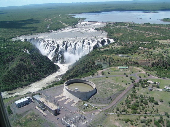
The River
The Ruacana Falls is situated in the Kunene river in northern Namibia. After a southbound run, the river makes a right turn to flow directly to the Atlantic, creating a natural setting for the Ruacana hydroelectric scheme. From here, on the bank of the Kunene River, Namibia draws most of it's life-sustaining power. To accommodate the three 80 megawatt turbine generators, as well as transformers, the switchgear, and the entry and discharge tunnels, more than 400 thousand cubic meters of rock had to be removed. Water from the Kunene River is regulated by a series of dams and a diversion weir, to channel part of the flow to a surge head bay on top of the mountain.
The Powerstation
The water drops almost 134m down vertical shafts into the heart of the mountain, where it drives the turbines before rejoining the Kunene from a discharge tunnel. When in full operation, the three turbines can generate about 330 Megawatts, which is fed into the Namibia Power Grid at 330 000 volts. Today the Ruacana hydroelectric power station is still the core of Namibia's power supply system. The first component of the Ruacana hydraulic system is the Diversion Weir, situated in Angolan territory. The Weir consists of a concrete gravity overspill structure with flap gates to control flood regulation, also incorporating the pressure tunnel intake. From the Diversion Weir a 1 500m long Pressure Tunnel runs along the southern bank of the river, some 30m below the ground.
After crossing the border the Pressure Tunnel continues through a fault zone in the Palmwash ravine, then pours into an oval shaped Surge Headbay, 31.5m in depth. The Surge Headbay is connected to an underground powerhouse complex consisting of three large parallel caverns, draft tubes and interconnecting galleries and ducts. The larger cavern houses the machine hall, turbines, a control building and the workshop area. Next to the cavern is the 120m long Transformer Hall, just above the horizontal section of the Penstocks. A third chamber on the southern side if the machine forms the Surge chamber, 70m long and 28m high. From here a 675m long Tailrace Tunnel discharges water to the river in correspondence with the Hippo Pool. The Access Gallery of 300m connects the caverns with the outside. On the surface next to the Surge Headbay, a switchgear lift and diesel building is located.
Geology
The large blocks of porphyroblastic gneiss, pink to grey in colour, characterise the geology at Ruacana, with incidental intercalation of chlorite-schists, hornblende schists and mica-schists materials.
bak to top
Powerhouse Complex
Situated 130m deep inside the hill south of the Palmwash, the Powerhouse Complex consists of three long caverns, parallel to each other with appurtenant trenches and recesses and their interconnecting galleries. The largest of the three caverns is the Machine cavern with the ability to house four 80 MW generators with their turbines housed in the central part. At the western and eastern end respectively are a large four-story Control Building and the Workshop Area. The cavern is 141.5m long, 16m wide and 36.5m high and is connected to the outside by a 360m long access gallery for vehicle transit.
Some 75 000m³ of concrete has been applied underground, mainly for the encasement of draft tubes and turbines - part in the tunnels and shafts and part in the Powerhouse Complex. The concrete was transported by truck mixers. Plain, mild and high intensity steel was used - a total of 3 500 tons. Temperature control was performed to ensure that fresh concrete, when placed in the final position did not exceed 25ºC. Shotcrete was made for underground permanent lining and used for the access gallery, the roof of the tailrace tunnel, the roofs of the machine hall and surge chamber as well as the roofs and halls of the transformer hall. A total of 3 700m³ underground shotcrete was mainly supported by 2.88 and 7.7 kg/m² of steel fabric. Additives were adapted for faster setting and hardening of the shotcrete.
bak to top
Pressure Tunnel
The 1 500m long pressure tunnel starts in Angolan territory at the eastern end of the Diversion Weir. After an initial downward slope of 1:17.5 degrees, the tunnel flattens slightly, reaching its lowest point 1 200m further, where it reaches the Palmwash ravine. From here the tunnel grades upwards (1:7.2) until it reaches the Surge Headbay.
Tunnel Supports:
Various methods of support were used during the excavations with steel mesh, rockbolts and prestressed cables, shotcrete and gunite being the methods used most frequently.
bak to top
Surge Headbay
Positioned partway down the hillside on favourable rock conditions is the oval shaped Surge Headbay - a large reservoir with a water surface area of about 3000m² and an internal wall depth of 31.5m. In the centre of the northern wall, a bellmouth inlet from the pressure tunnel guides the flow by a baffle structure set on the headbay floor.
Opposite the tunnel entry, blocks for four penstock intakes are positioned, including a transition piece into which gate frames are welded to hold in place the circular horizontal legs of the penstocks terminating at a flange coupled to that of a PIV penstock inlet valve. Foundations for the headbay, some 12m below ground level, require excavation for 115 000m³. The spoil was used to fill the terraces for parking area and for backfilling of the headbay structure.
The total concrete placed in the Surge Headbay came to about 75 000m³.
bak to top
Tailrace Tunnel
Sloping down to the Crocodile Pool at a low gradient (1:685), The Tailrace Tunnel was designed to operate normally under freeflow conditions, but can also be submerged in times of severe flooding. The tunnel outfall is set roughly 7m below river level. Favourable rock conditions enabled the use of shotcrete for the roof, but the wall and invert were finished off with concrete. the outfall structure, at the tunnel portal, provides for the stoplog gates, the piers, an access bridge and the associated stoplog storage sheds. Access in the sidewall provides for the installation of pumps for draining the tailrace behind the stoplogs.
bak to top
Access Gallery
The 360m long Access Gallery meets the machine Hall and the Transformer Hall at their eastern ends. The excavation of the modified horseshoe shape gallery was performed by perimeter drilling to achieve a regular rock surface, suited to final shotcrete. Mesh support and mechanically anchored rockbolts, 3.5m long with 100KN capacity, were used on fractural material. A total excavation of 26 500m³ was required, including a lateral channel for the pipes and cables and the 18m extensions between the Machine caverns and Transformer Hall.
bak to top
Camps and Services
The Ruacana Escarpment Town, some 25km from the work site, is where staff and artisans are accommodated, together with other members of the public who settled over time. Full road, power, water and sewerage services exist. Other facilities include a medical clinic, primary school, post office bank and general stores. Multicore land telephone lines connect both the town and the worksite to the outside world. The main work centers are all connected by an extensive internal telephone system with automatic switchboard.